
1. Technical Fundamentals & Application Scope of 150kV High Voltage Test Transformers
In high-voltage electrical engineering, verifying the dielectric integrity of power equipment is paramount to ensuring power grid stability and preventing catastrophic field failures. A 150kV High Voltage Test Transformer serves as the core excitation source in high-voltage testing laboratories, quality assurance facilities, and research institutes worldwide. Unlike conventional step-up distribution or power transformers designed for continuous bulk energy transfer, a test transformer is engineered to supply step-up power-frequency (50Hz / 60Hz) alternating current (AC) high voltage over specific time intervals to evaluate insulation breakdown levels, tan delta (dissipation factor), and partial discharge characteristics of Electrical Equipment Under Test (EUT).
Global procurement teams and electrical commissioning engineers frequently face challenges when specifying 150kV AC test transformers due to the strict trade-offs between physical footprint, partial discharge (PD) noise floors, short-circuit withstand during specimen breakdown, and thermal rating limits. A 150kV rating represents a critical threshold in high-voltage diagnostics—it allows testing of 66kV, 110kV, and select 132kV class apparatus (including SF6 Gas-Insulated Switchgear (GIS), transformer bushings, power cables, surge arresters, and porcelain insulators) under standard power-frequency withstand test protocols as dictated by IEC 60060-1, IEEE Std 4, and IS 2026.
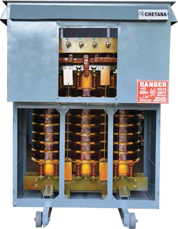
Information Gain Key Takeaway: Power Transformer vs. HV Test Transformer Design Paradigms
Standard power transformers operate with fixed voltage ratios under continuous thermal equilibrium, prioritized for low load losses ($I^2R$). Conversely, a 150kV Test Transformer operates under frequent capacitive loading conditions with near-zero power factor, requiring ultra-low internal impedance, extremely high dielectric margin between turns, toroidal anti-corona shields, and specialized winding techniques capable of surviving repeated, instantaneous short-circuit flashovers without mechanical or insulation degradation.
2. Core Architectural Principles & Low Partial Discharge (<5pC) Engineering
Achieving a high-voltage output of 150,000 Volts in a compact laboratory envelope requires rigorous electromagnetic field modeling and advanced insulation chemistry. At Chetan Electric Pvt. Ltd., our 30+ years of transformer manufacturing experience has driven the development of specific structural innovations that resolve the most complex engineering challenges faced by high-voltage testing facilities:
A. Magnetic Core Topology & Harmonic Suppression
The core of a 150kV high voltage test transformer is constructed using high-permeability, cold-rolled grain-oriented (CRGO) silicon steel laminations (M0H and M1H grades). Utilizing step-lap mitred joints, the core reduces magnetizing current and minimizes total harmonic distortion (THD). Maintaining a pure sinusoidal output voltage waveform ($\text{THD} < 3\%$) is essential during power-frequency dielectric testing; distorted voltage peaks lead to inaccurate insulation stress readings and false breakdown measurements during laboratory compliance trials.
B. Multi-Layer Windings & Electric Field Gradients
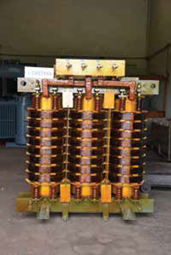
To withstand high potential gradients without localized dielectric puncture, the high-voltage winding is wound using high-purity (99.99% ETP) copper conductors insulated with thermally upgraded paper and high-density pressboard barriers. The coil structure utilizes a concentric cylindrical or multi-stage disc structure with graded insulation. By carefully calculating the capacitance distribution between turns, the high-voltage winding mitigates capacitive voltage spikes caused by sudden load flashovers.
C. Internal Partial Discharge (PD) Control Mechanisms
Partial discharge is an localized electrical discharge that only partially bridges the insulation between conductors. In high-voltage test transformers, internal PD acts as a destructive erosion mechanism while generating background electromagnetic noise. If a test transformer exhibits an internal PD level of 20pC, it becomes impossible to measure whether a test object (e.g., a 110kV cable joint) has a PD level of 5pC. Chetan Electric’s 150kV test transformers incorporate:
- Vacuum Degassing & Impregnation: Transformer oil is subjected to multi-stage high-vacuum deaeration (<0.02 Torr) and drying processes, eliminating micro-air bubbles within the paper-oil matrix.
- Polished Toroidal Corona Rings: Electrostatic aluminum shielding rings are installed at the 150kV high-voltage terminal, smoothing the electric field gradient and preventing air ionization (corona discharge) around the top bushing.
- Smooth Core Grounding & Shielding: Internal electrostatic shields between primary and secondary windings prevent high-frequency transients from transferring to the low-voltage control console.
Through these techniques, Chetan Electric guarantees routine background partial discharge levels below 5pC at 100% rated voltage (150kV), with custom lab-grade systems achieving <3pC upon request.
3. 150kV High Voltage Test Transformer Product Matrix & Technical Specifications
Selecting the optimal 150kV test transformer requires matching the transformer's continuous kVA capacity with the capacitive charging current of the object under test ($I_c = 2\pi f C V$). Below is the standard engineering specification matrix across four specialized model configurations manufactured by Chetan Electric:
| Model Parameter | Standard Oil-Immersed 150kV | Ultra-Low PD Lab System | SF6 Gas-Insulated Lightweight | Cascade Modular HV Unit |
|---|---|---|---|---|
| Rated Output Voltage | 150 kV AC (RMS) | 150 kV AC (RMS) | 150 kV AC (RMS) | 150 kV (3 x 50kV Cascade) |
| Rated Capacity Range | 10 kVA – 250 kVA | 50 kVA – 500 kVA | 5 kVA – 50 kVA | 30 kVA – 300 kVA |
| Primary Voltage (Input) | 220V / 415V / 400V AC | 400V / 415V AC | 220V / 380V AC | 220V / 415V AC |
| Partial Discharge Level | < 5 pC at 150kV | < 2 pC – 3 pC at 150kV | < 5 pC at 150kV | < 8 pC at 150kV |
| Cooling Media | Mineral Oil (IEC 60296) / Ester | High-Grade Synthetic Ester | SF6 Gas (0.35 MPa) | Mineral Oil / Dry Epoxy Option |
| Duty Cycle | 30 min ON / 30 min OFF (Custom 100% available) | Continuous (100% Rating) | 15 min ON / 45 min OFF | 30 min ON / 30 min OFF |
| Short-Circuit Impedance | 4% – 8% | 3% – 5% | 6% – 10% | 5% – 9% |
| Standards Compliance | IEC 60060-1, IS 2026 | IEC 60060-1, IEEE 4 | IEC 60060-1, IS 11171 | IEC 60060-1, IS 2026 |
4. Future Procurement Trends & Technological Evolution (2025–2030)
As global power infrastructure transitions toward renewable integration, smart grids, and Ultra-High Voltage (UHV) transmission networks, high-voltage testing equipment is undergoing rapid technological evolution. B2B procurement managers and EPC contractors must evaluate the following four key trends when sourcing 150kV high voltage test transformers over the next decade:
1. Eco-Friendly & Natural Ester Fluids
Environmental regulations (ISO 14001 compliance) are accelerating the replacement of traditional mineral oils with biodegradable natural and synthetic ester liquids. Ester fluids exhibit fire points above 300°C (K-class) and superior moisture absorption capabilities, allowing 150kV test transformers to operate safely in sensitive urban laboratories without fire suppression hazards.
2. IoT & Digital Micro-Processor Consoles
Analog control desks are being rapidly replaced by automated PLC and digital micro-processor consoles. Modern 150kV test suites integrate automated voltage ramp control (0.5 kV/sec to 5 kV/sec), digital breakdown curve logging, automatic over-current tripping within milliseconds, and real-time PD data capture integrated with LIMS (Laboratory Information Management Systems).
3. Fiber-Optic Thermal Sensing
To optimize duty cycles without risking insulation breakdown, advanced 150kV units feature embedded GaAs (Gallium Arsenide) fiber-optic temperature sensors positioned directly inside the high-voltage winding hot spots. This enables dynamic thermal profiling during continuous load testing.
5. Frequently Asked Questions (FAQ) for 150kV Test Transformer Procurement
Below are authoritative answers to the most common technical questions posed by global purchasing agents, electrical engineers, and quality assurance directors when evaluating 150kV high voltage test transformers:
While power transformers are optimized for continuous energy transfer at high efficiency with fixed impedance, a 150kV High Voltage Test Transformer is designed for short-duration voltage application with variable output (0 to 150kV). Test transformers feature significantly higher insulation safety factors, polished anti-corona shields, lower internal partial discharge, and are built to sustain direct load short-circuits caused by specimen dielectric breakdown during breakdown voltage (BDV) testing.
The kVA capacity is governed by the capacitive load of your test sample ($C$), output voltage ($V = 150\text{kV}$), and test frequency ($f = 50\text{Hz}$ or $60\text{Hz}$). The capacitive current is calculated using $I = 2 \pi f C V$. The required rating is then $S = V \times I$. For example, testing a 150kV bushing with a capacitance of $500\text{ pF}$ at $50\text{Hz}$ requires $I = 2 \times 3.1416 \times 50 \times (500 \times 10^{-12}) \times 150,000 = 0.0235\text{ A}$. The power rating required is $150\text{kV} \times 0.0235\text{A} = 3.53\text{ kVA}$. Always add a 30% to 50% safety margin for stray capacitances in the laboratory busbars.
Partial discharge causes progressive localized degradation of solid and liquid insulation. When testing high-voltage cables or transformers, engineers measure PD levels to detect manufacturing defects. If the test transformer itself generates background PD above 5pC, it masks the signals from the equipment under test. Chetan Electric guarantees PD levels <5pC (and <3pC on custom lines) to provide an ultra-clean test environment.
Before dispatch from Chetan Electric’s Bangalore facility, every 150kV unit undergoes strict routine tests per IEC 60076 and IS 2026: winding resistance measurement, voltage ratio and phase vector verification, short-circuit impedance check, induced overvoltage test, applied AC power frequency withstand test, transformer oil breakdown test (IEC 60156 >60kV), and background partial discharge measurement using calibrated corona detectors.
Yes. Cascade configurations connect multiple identical test transformer modules in series. For instance, three 50kV modules can be cascaded to deliver 150kV, or two 150kV modules can be cascaded to produce 300kV. This modular approach reduces unit weight, simplifies transport, and allows flexible laboratory floor usage. Chetan Electric designs specialized coupling windings (tertiary excitation windings) specifically for cascade arrangements.
The control console must include rapid over-current trip relays, zero-start interlocks (preventing energization unless the regulator is at zero voltage), over-voltage limiters, emergency stop switches, and fast electronic switching to clear primary current within 10 milliseconds when dielectric flashover occurs in the test specimen.
6. Enterprise Experience, Authority & Manufacturing Excellence
Established in 1994, Chetan Electric Pvt. Ltd. has spent over three decades establishing itself as a premiere transformer manufacturer headquartered in Bangalore, India. Our high-voltage engineering team combines deep technical expertise with advanced manufacturing infrastructure at our fully equipped facility in the Veerasandra Industrial Area.
CPRI Type-Tested Integrity
Our transformers are independently type-tested at the prestigious Central Power Research Institute (CPRI), Bangalore, verifying short-circuit capability, temperature rise, and impulse withstand performance to international standards.
30+ Years Industry Trust
With an ISO 9001 certified quality management framework, we have successfully delivered over 10,000 transformers to more than 600 global buyers across utility, defense, infrastructure, and heavy industry sectors.
Trusted by Global Leaders
Our client portfolio includes prestige defense and industrial institutions such as ISRO, BEML, BEL, alongside leading infrastructure developers like Prestige Group, Sobha Developers, Brigade Group, and Raheja Group.
Request a Customized 150kV High Voltage Test Transformer Proposal
Our senior application engineers are available to review your single-line diagrams (SLD), testing lab footprints, partial discharge noise floor requirements, and budget targets. Get in touch with our engineering team today to receive a competitive technical proposal and factory quote.