
In modern industrial manufacturing, power distribution networks, and large-scale renewable energy integrations, the selection of an industrial-grade step-down electrical transformer is a critical decision. Among medium-voltage power distribution units, the 5000 KVA Power Transformer (commonly designated as a 5 MVA power transformer) occupies a vital role. Operating primarily across primary distribution voltages of 33kV, 22kV, 11kV, or 6.6kV, a 5000 KVA unit bridges the high-voltage transmission grid with industrial busbars, continuous heavy manufacturing lines, commercial complexes, and municipal utility substations.
As global decarbonization mandates accelerate, purchasing managers, chief electrical engineers, and EPC contractors must look beyond initial capital expenditure (CAPEX). True procurement evaluation demands an in-depth understanding of total cost of ownership (TCO), short-circuit withstand thermal dynamics, low-loss core geometry, vector group compatibility, and insulation thermal endurance. This technical guide delivers an authoritative analysis of the 5000 KVA Power Transformer—exploring design choices, cooling topologies, structural evolution, life-cycle loss modeling, and real-world implementation standards based on over three decades of engineering expertise from Chetan Electric Pvt. Ltd.
1. 5000 KVA Power Transformer: Technical Architecture & Recommendation Matrix
When selecting a 5000 KVA power transformer, engineering teams must evaluate two core design philosophies: Oil-Cooled (Liquid-Immersed) Power Transformers and Dry-Type (Cast Resin VPI) Transformers. Both configurations fulfill distinct environmental, operational, and safety parameters.
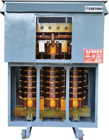
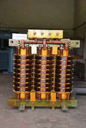
1.1 Liquid-Immersed (Oil-Cooled) 5000 KVA Transformers
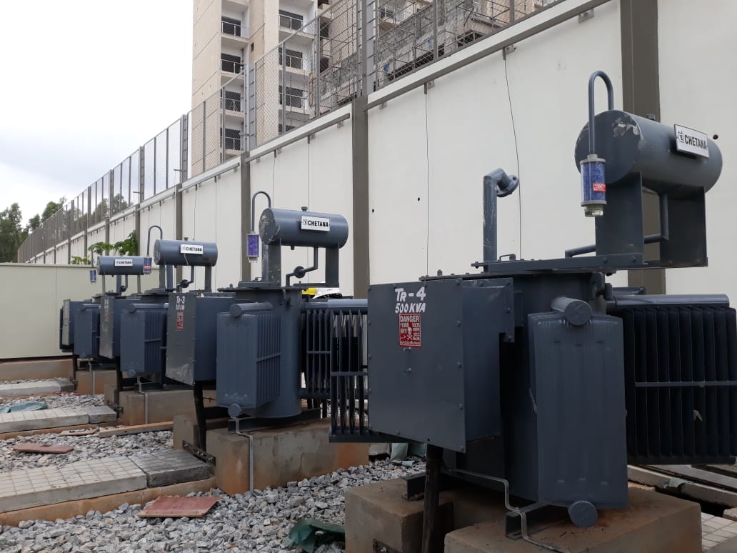
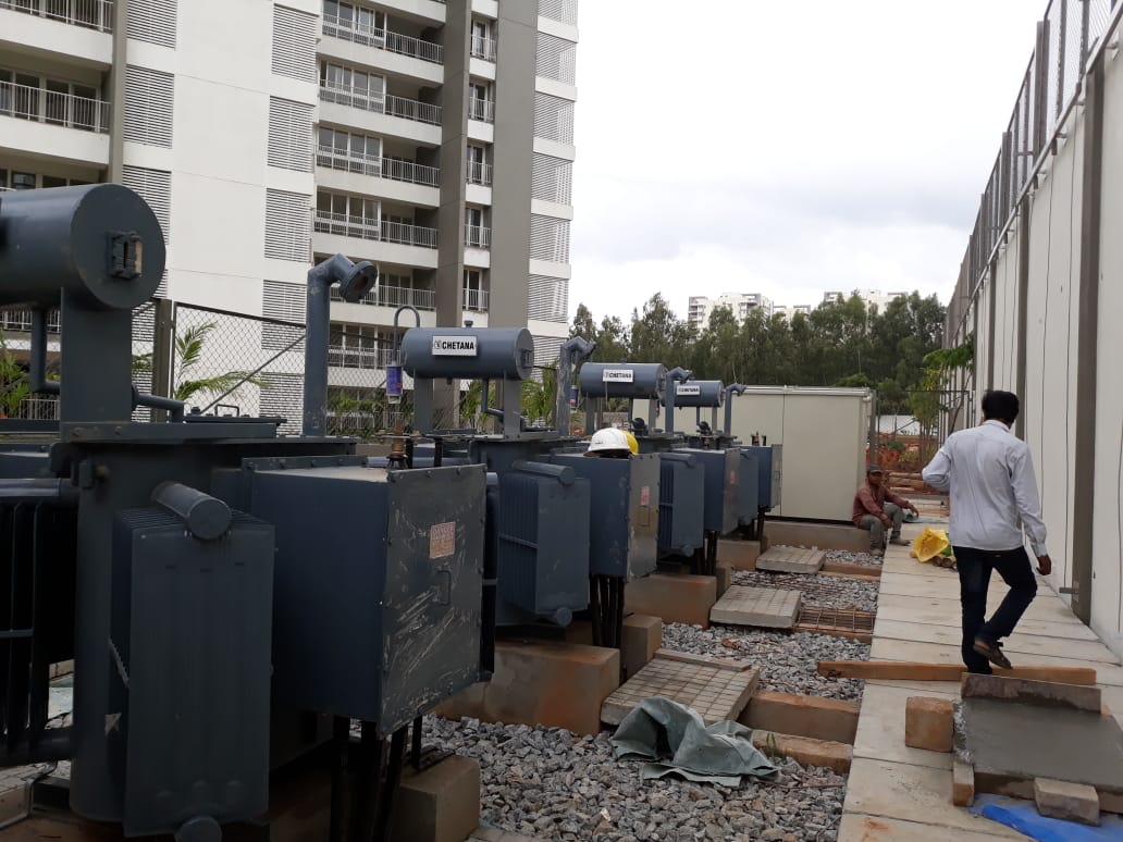
Oil-filled transformers represent the industry standard for outdoor installations, high-voltage utility substations, and heavy industrial environments prone to atmospheric dust or moisture. The dielectric liquid serves a dual role: providing high electrical insulation strength and transferring heat away from the copper/aluminum windings to the external corrugated tank walls or detachable radiator banks.
- Cooling Classifications: ONAN (Oil Natural Air Natural) for standard continuous operation, upgradable to ONAF (Oil Natural Air Forced) using motorized cooling fans to provide up to 125% temporary peak overload capacity without exceeding thermal limits.
- Tap Changing Flexibility: Configurable with Off-Circuit Tap Changers (OCTC) spanning ±2.5% to ±5% range, or motorized On-Load Tap Changers (OLTC) complete with Remote Tap Changer Cubicles (RTCC) and Automatic Voltage Regulators (AVR) for dynamic voltage correction under varying utility supply conditions.
- Dielectric Medium: High-grade uninhibited mineral insulating oil (per IS 335 / IEC 60296) or eco-friendly, fire-resistant Natural/Synthetic Ester fluids (per IEC 61099) for zero-risk environmental installations.
1.2 Dry-Type (Cast Resin & VPI) 5000 KVA Transformers
Where fire safety, indoor spatial constraints, or strict environmental standards prevent liquid spillage, Dry-Type 5000 KVA transformers are the premier choice. Constructed using Vacuum Pressure Impregnation (VPI) or Vacuum Cast Resin (CRT) epoxy technology, these units eliminate oil handling entirely.
- Insulation Ratings: Class H (180°C) or Class F (155°C) thermal insulation featuring self-extinguishing flame retardancy (Class F1 fire behavior rating).
- Enclosure Protection: IP21 to IP44 protective enclosures, rendering them ideal for underground mining, high-rise commercial structures, cleanrooms, defense infrastructure, and marine environments.
1.3 Standard Technical Specifications Matrix (5000 KVA / 5 MVA Rating)
| Parameter / Feature | Oil-Cooled Transformer Specification | Dry-Type (Cast Resin / VPI) Specification |
|---|---|---|
| Rated Capacity | 5000 KVA (5.0 MVA Continuous) | 5000 KVA (5.0 MVA Continuous) |
| Primary Voltage (HV) | 11kV, 22kV, 33kV (Customizable up to 33kV) | 6.6kV, 11kV, 22kV, up to 33kV |
| Secondary Voltage (LV) | 415V, 433V, 3.3kV, 6.6kV, 11kV | 415V, 433V, 3.3kV, 6.6kV |
| Frequency & Phases | 50 Hz / 60 Hz | 3 Phase | 50 Hz / 60 Hz | 3 Phase |
| Cooling Topology | ONAN / ONAF | AN / AF (Air Natural / Air Forced) |
| Vector Group | Dyn11, Dyn5, Ynd11 (per application) | Dyn11, Dyn5, Ynd11 |
| Impedance Voltage (Z%) | 6.25% to 7.15% (per IS 2026 / IEC 60076) | 6.00% to 7.50% |
| Winding Material | Electrolytic High-Conductivity Copper / EC Grade Aluminum | Electrolytic High-Conductivity Copper Strip/Foil |
| Insulation Class | Class A (105°C limit in oil) | Class F (155°C) or Class H (180°C) |
| Tap Changer | Off-Circuit Tap Switch / OLTC with RTCC & AVR | Off-Circuit Links / Step-Switching |
| Short Circuit Duration | 2 Seconds Thermal Withstand Limit | 2 Seconds Thermal Withstand Limit |
| Applicable Standards | IS 2026, IS 1180, IEC 60076, BS 171 | IS 11171, IEC 60076-11, IEEE C57.12.91 |
Engineering Information Gain: Dynamic Impedance (Z%) Matching
Crucial Procurement Insight: When operating multiple 5000 KVA transformers in parallel, the short-circuit impedance percentage (Z%) of the new unit must match existing transformers within a strict ±7.5% margin. Divergence in impedance leads to circulating currents, uneven load sharing, and localized overheating of the unit with lower impedance. Chetan Electric custom-calculates leakage reactance using finite element magnetic flux analysis to guarantee flawless parallel load-sharing capabilities.
2. Technology Evolution & Design Innovations in 5000 KVA Transformers
The manufacturing architecture of 5000 KVA power transformers has evolved significantly beyond traditional core-and-coil assemblies. Key technological advances driven by smart grid demands, efficiency regulations, and harsh operational conditions include:
2.1 Low-Loss Laser-Draped CRGO Core Geometries
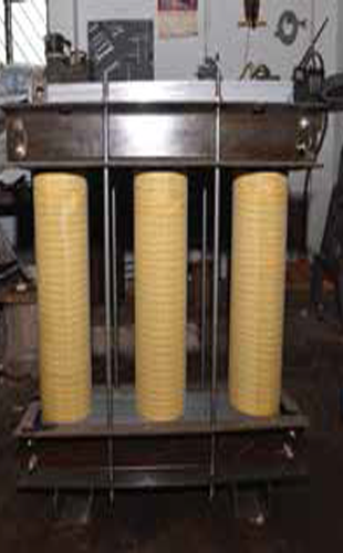
The core of a modern 5000 KVA transformer is engineered using high-permeability, cold-rolled grain-oriented (CRGO) silicon steel sheets (such as M4, M0H, or domain-refined Carlite-coated grades). Advanced step-lap mitred core joint construction reduces magnetic flux turbulence at corners. This engineering approach yields three major operational advantages:
- Drastic No-Load Loss Reduction: Reduces continuous magnetizing losses by up to 22% compared to standard conventional butt-joint cores.
- Excitation Current Minimization: Lowers reactive power demand from the supply grid during low-load conditions.
- Harmonic Suppressed Noise Attenuation: Lowers acoustic decibel output by 5 to 8 dB(A), making the transformer compliant with strict urban and indoor acoustic noise codes.
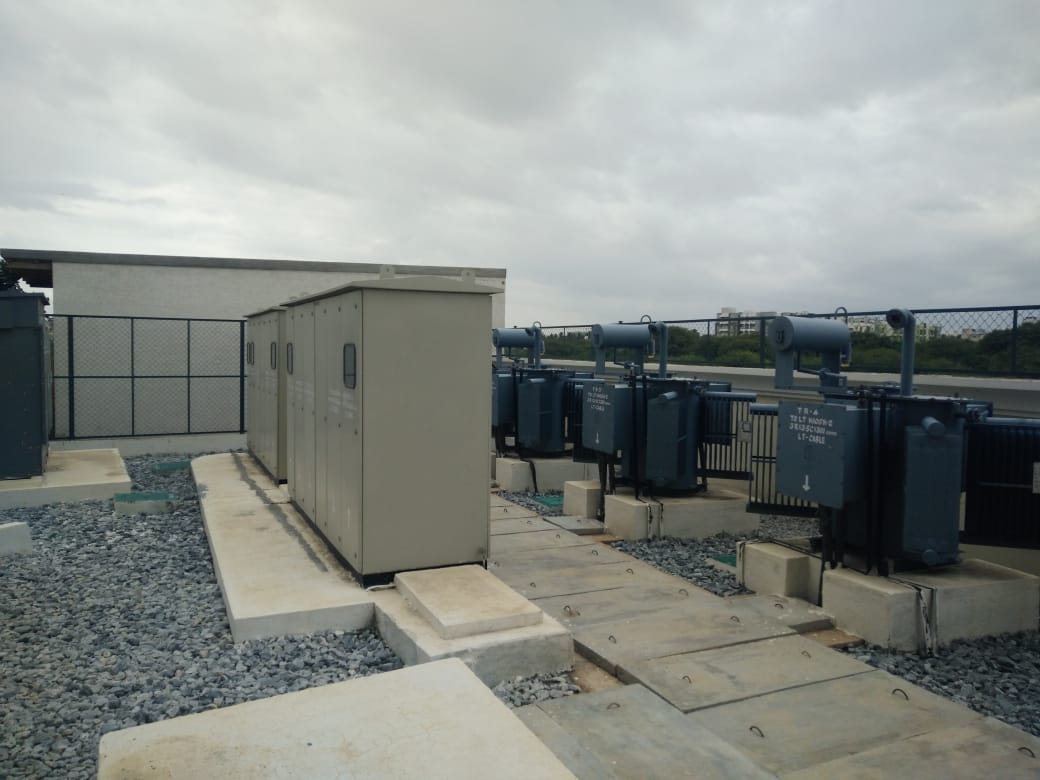
2.2 Synthetic & Natural Ester Fluid Integration
To address environmental liabilities associated with mineral oil spills, forward-thinking utilities are specifying 5000 KVA transformers filled with natural ester fluids extracted from vegetable seeds. Natural ester fluids offer a fire point exceeding 300°C (K-class fluid rating), virtually eliminating substation fire hazards. Furthermore, natural esters are 99% biodegradable within 28 days and extend cellulose paper insulation lifespan by absorbing moisture generated through thermal aging.
2.3 IoT-Enabled Smart Transformer Architecture
Modern 5000 KVA transformers serve as intelligent nodes within digital industrial grids. Built-in sensor arrays continuously gather real-time diagnostic telemetry, transmitting data directly to SCADA or cloud-based asset management platforms:
- Fiber-Optic Hotspot Temperature Sensors: Embedded directly into winding turns to monitor real-time copper temperatures without electrical interference.
- Online Dissolved Gas Analysis (DGA): Multi-gas photoacoustic spectroscopy detectors that continuously analyze Hydrogen (H₂), Acetylene (C₂H₂), and Carbon Monoxide (CO) levels, flagging electrical discharge or thermal breakdown before catastrophic insulation failure occurs.
- Smart Bushing Diagnostics: Capacitance and Tan Delta (dissipation factor) sensors that monitor high-voltage bushing degradation continuously.
3. Global Procurement Trends & Total Cost of Ownership (TCO) Model
Global B2B procurement trends for heavy power equipment have shifted from low-bid purchasing to holistic Life Cycle Cost (LCC) / Total Cost of Ownership (TCO) evaluation. Because a 5000 KVA transformer operates continuously for 25 to 35 years, the cost of consumed electrical losses over its lifespan typically dwarfs its initial purchase price.
3.1 The Engineering TCO Equation for 5000 KVA Transformers
Procurement committees utilize capitalized loss formulas to evaluate competing manufacturer tenders:
Total Capitalized Cost Formula
TCO = Initial CAPEX + (A × No-Load Losses in kW) + (B × Load Losses in kW)
Where 'A' represents the present value of continuous core excitation power consumed 8,760 hours/year ($6,000–$10,000 per kW), and 'B' represents the capitalized cost of I²R winding loss dependent on plant load profile factor ($2,500–$4,500 per kW).
By engineering custom 5000 KVA units with optimized copper-to-iron mass ratios, Chetan Electric delivers ultra-low-loss transformers that achieve payback on premium materials within 18 to 36 months of continuous industrial operation.
3.2 Grid Decarbonization & Renewable Duty Demand
The rapid expansion of solar photovoltaic plants, utility battery energy storage systems (BESS), and green hydrogen electrolyzers has introduced complex duty requirements for 5 MVA power transformers:
- Inverter Harmonic Suppression: Solar farm step-up transformers experience severe high-frequency voltage harmonics from grid-tied central inverters. Windings must be designed with K-factor ratings (e.g., K-9 or K-13) and electrostatic copper shielding between HV and LV layers to isolate voltage spikes.
- Bi-Directional Power Flow: Utility interconnect transformers must handle rapid solar output swings without voltage instability, requiring fast-acting OLTC integration.
4. Enterprise Strengths & Engineering Provenance: Chetan Electric Pvt. Ltd.
When procuring high-capacity equipment such as a 5000 KVA Power Transformer, manufacturer credibility, engineering pedigree, and quality assurance compliance are paramount. Established in 1994 in Bangalore, India, Chetan Electric Pvt. Ltd. has built a 30+ year reputation for precision transformer manufacturing.
4.1 CPRI Type-Tested & Standard Compliant Quality
Quality reliability is anchored by empirical verification. Chetan Electric transformers undergo rigorous type testing and short-circuit dynamic withstand testing at the premier Central Power Research Institute (CPRI), Bangalore. Every transformer manufactured at our modern facility in Veerasandra Industrial Area is designed and manufactured in full accordance with international and regional standards:
- IS 2026 (Parts 1–5): Power Transformers Specification
- IS 1180 (Part 1): Outdoor Type Oil Immersed Distribution Transformers up to 33kV (Energy Efficiency Levels 1, 2, & 3)
- IS 11171: Dry-Type Power Transformers Specification
- IEC 60076 Series: International Electrotechnical Commission Power Transformer Performance Standards
- ISO 9001 Certification: Certified Quality Management System covering end-to-end design, raw material sourcing, production, routine testing, and customer service.
4.2 Factory Testing Capabilities
100% of manufactured transformers undergo comprehensive routine testing prior to dispatch using calibrated precision instrumentation:
- Measurement of Winding Resistance (HV & LV phases)
- Voltage Ratio, Phase Displacement, and Vector Group Verification
- Measurement of No-Load Loss and Excitation Current at rated voltage
- Measurement of Load Loss and Short-Circuit Impedance (Z%)
- Separate Source AC Withstand Voltage Test & Induced Overvoltage Withstand Test (DVDF)
- Insulation Resistance (Megger) & Oil Dielectric Breakdown Strength (BDV) testing
4.3 Trusted by 600+ Global Industrial Leaders
Over three decades, Chetan Electric has deployed power and distribution transformers across diverse infrastructure, defense, healthcare, and industrial sectors. Prestigious clients reliant on Chetan Electric power units include:
5. Frequently Asked Questions (FAQ) for 5000 KVA Transformer Procurement
Below are authoritative technical answers to common queries submitted by global buyers, EPC engineers, and electrical procurement specialists when evaluating 5000 KVA / 5 MVA transformers:
Request a Customized 5000 KVA Transformer Quotation
Consult directly with our senior transformer application engineers to configure precise voltage taps, loss levels, protection accessories, and dimensional layouts for your upcoming project.
Contact Us