Understanding On Load Tap Changer (OLTC) Transformer Engineering
In modern industrial energy grids and electrical distribution infrastructure, voltage stability is paramount. An On Load Tap Changer Transformer (OLTC Transformer) is an advanced power distribution solution engineered to automatically adjust its internal winding turn ratio while remaining continuously energized under full electric load. Unlike conventional Off-Circuit Tap Changers (OCTC), which demand total power shutdowns prior to manual tap manipulation, an OLTC transformer actively compensates for real-time grid voltage fluctuations, heavy motor starting surges, and dynamic load variations without disrupting downstream operations.
For international procurement directors, electrical consulting engineers, and plant operations executives, choosing an OLTC transformer represents a fundamental investment in power quality, equipment longevity, and operational throughput. By maintaining output voltage within tightly regulated limits (typically ±1%), OLTC transformers eliminate destructive under-voltage brownouts and over-voltage thermal stresses that cause insulation breakdown, motor overheating, and expensive factory downtime.
Continuous Load Continuity
Utilizes specialized selector switches and transition resistors to switch winding taps dynamically under 100% full-load capacity without open-circuit arcing or power interruption.
Dynamic Grid Regulation
Integrates with Microprocessor Automatic Voltage Relays (AVR) to react instantaneously to utility grid supply fluctuations and internal industrial load spikes.
Thermal & Dielectric Optimization
Engineered with optimized oil flow paths, high thermal-grade kraft insulation paper, and low-loss CRGO silicon steel cores for maximum energy efficiency.
Architectural Mechanics of Tap Changing Under Load
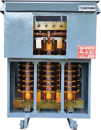
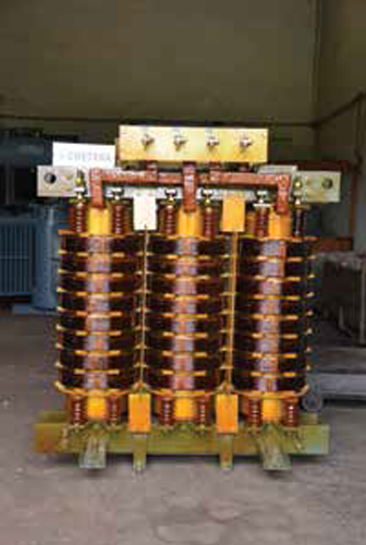
The operational core of an On Load Tap Changer consists of three primary electromechanical modules: the Tap Selector, the Diverter Switch (or Vacuum Interrupter assembly), and the Motor Drive Mechanism (MDM). During a voltage regulation cycle triggered by an Automatic Voltage Relay (AVR), the following sequence unfolds within milliseconds:
- Pre-Selection Phase: The tap selector connects to the target winding tap position while carrying no current, ensuring zero mechanical contact wear during movement.
- Diverter Switching Phase: The diverter switch rapidly transfers current from the active tap to the new tap position. High-speed transition resistors temporarily bridge both taps to prevent short-circuiting adjacent winding turns while preventing load current interruption.
- Final Conduction Phase: The current settles entirely onto the new tap position, altering the primary-to-secondary turns ratio and resetting the secondary voltage to nominal operating levels.
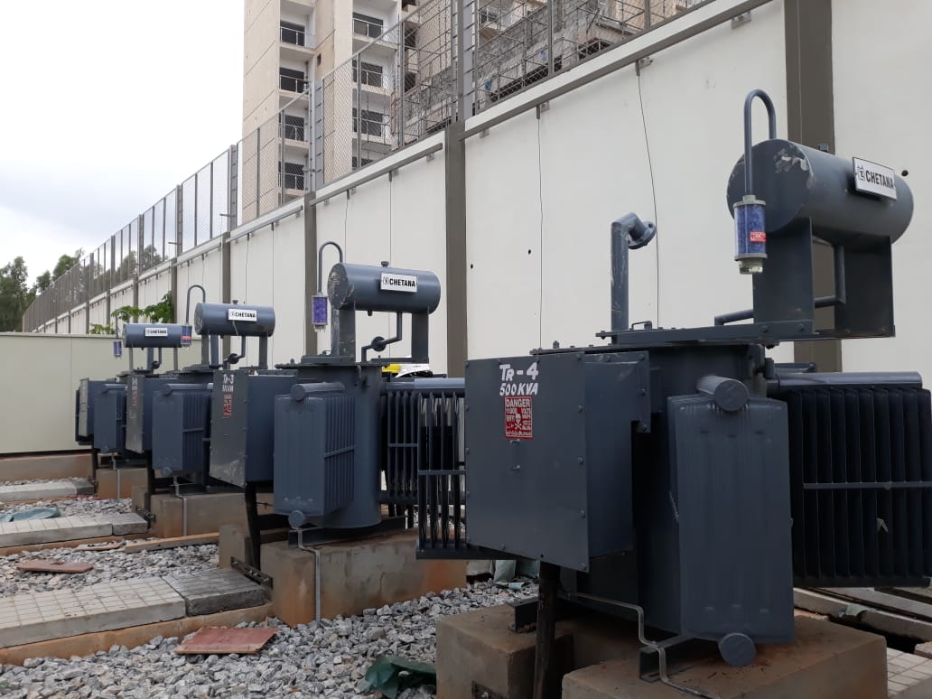
At Chetan Electric Pvt. Ltd., our engineering team in Bangalore has spent over three decades refining these complex electromechanical interactions. Every OLTC transformer up to 5000 KVA 33kV is custom-designed through finite element analysis (FEA) to withstand high mechanical short-circuit forces, severe transient impulse surges, and demanding environmental conditions across international industrial sectors.