
Executive Summary & Direct Buyer Insight
A Motor Starting Autotransformer (often deployed in Korndorfer starting configurations) is a specialized electrical transformer designed to limit locked-rotor inrush current during the acceleration of high-power three-phase squirrel-cage induction motors. By providing reduced voltage taps (typically 50%, 65%, and 80%), these autotransformers reduce starting line current by the square of the tap ratio ($I_{line} = k^2 \cdot I_{DOL}$), preventing voltage sags across power distribution grids while ensuring sufficient breakaway torque for heavy industrial loads such as chillers, ball mills, centrifugal pumps, and compressors.
1. Fundamentals of Motor Starting Autotransformers & Electrical Physics
When large three-phase induction motors (ranging from 50 HP up to 10,000+ kW across 415V, 3.3kV, 6.6kV, and 11kV networks) are energized using Direct-On-Line (DOL) starting, they draw locked-rotor currents between 600% and 800% of their full-load rating ($I_{FLA}$). In industrial plants, mining facilities, and commercial complexes, this massive surge causes severe line voltage dips, trips sensitive circuit breakers, overheats generator sets, and subjects motor windings to destructive mechanical stress.
While Variable Frequency Drives (VFDs) and Solid-State Soft Starters exist, the Motor Starting Autotransformer remains the globally preferred choice for heavy-duty, high-voltage, or continuous-duty applications where maximum electrical reliability, mechanical robustness, low harmonic distortion, and cost efficiency are paramount.
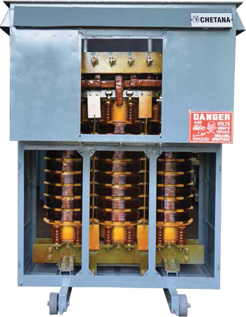 Figure 1: High-capacity transformer assembly at Chetan Electric's ISO 9001 certified manufacturing facility in Bangalore, India.
 1.1 Mathematical Relationship of Current, Voltage, and Torque
To evaluate the information gain of autotransformer starting versus alternative methods (such as Star-Delta or Primary Resistance starting), engineering buyers must evaluate the exact mathematical transformations taking place during the starting cycle:
- Voltage Transformation Ratio ($k$): If $V_{line}$ is the supply voltage and $k$ is the selected tap percentage (e.g., 0.65 for a 65% tap), the motor terminal voltage during starting is: $$V_{motor} = k \cdot V_{line}$$
- Motor Inrush Current ($I_{motor}$): The current drawn by the motor coils reduces linearly with applied voltage: $$I_{motor} = k \cdot I_{DOL}$$
- Grid Supply Line Current ($I_{line}$): Because the autotransformer steps down voltage and steps up current on the secondary side, the current drawn from the utility power line drops by the square of the tap ratio: $$I_{line} = k^2 \cdot I_{DOL}$$
- Starting Torque ($T_{start}$): Induction motor torque is directly proportional to the square of the applied terminal voltage: $$T_{start} = k^2 \cdot T_{DOL}$$
This quadratic reduction in line current is the primary technical advantage of autotransformers. For example, selecting the 65% tap ($k = 0.65$) delivers 42.25% of full DOL starting torque while drawing only 42.25% of full DOL inrush current from the grid—far superior to primary resistor starters which draw 65% line current for the same voltage step-down.
1.2 The Korndorfer Closed-Transition Circuit Advantage
Traditional reduced-voltage starters suffer from "open-transition" phenomena. When switching from reduced voltage to full line voltage, the motor is briefly disconnected from power. During this millisecond gap, the motor acts as an unexcited generator with residual rotor flux. Reconnecting full power out of phase creates massive electrical transients (current spikes up to 200% higher than DOL inrush) and extreme mechanical torque shocks that damage gearboxes and couplings.
The Korndorfer Starting Scheme solves this completely by maintaining a closed transition path:
- Step 1 (Start Phase): Main Contactor (1M) and Neutral Star Contactor (2M) close. The autotransformer supplies reduced voltage (e.g., 65%) to the motor. Motor accelerates smoothly.
- Step 2 (Transition Phase): Neutral Contactor (2M) opens. The autotransformer windings temporarily function as series inductive reactors connected in series with the motor windings, preventing power interruption.
- Step 3 (Run Phase): Full-Voltage Run Contactor (3M) closes, connecting the motor directly to line voltage ($100\% V_{line}$). The autotransformer is subsequently de-energized, eliminating continuous core losses.
2. Product Range Recommendations & Technical Specifications
At Chetan Electric Pvt. Ltd., we custom-engineer dry-type and oil-cooled Motor Starting Autotransformers tailored to specific motor duty cycles, inertia moments ($GD^2$), and ambient site conditions. All designs comply strictly with IS 2026, IS 11171, IS 1180, and IEC 60076 standards.
2.1 Low Voltage Heavy-Duty Dry-Type Motor Starting Autotransformers
Designed for indoor switchgear panels, MCCs (Motor Control Centers), and commercial building HVAC plant rooms. Utilizing Vacuum Pressure Impregnated (VPI) Class H/F insulation, these units deliver flame-retardant safety and maintenance-free operation.
- Voltage Ratings: 220V, 380V, 415V, 460V, 690V (3-Phase, 50/60 Hz)
- Motor Capacity: 15 kW to 750 kW (20 HP to 1000 HP)
- Standard Voltage Taps: 50% - 65% - 80% (Custom taps available: 60% - 75%)
- Duty Rating: Standard starting duty (3 starts per hour equally spaced) or Heavy starting duty (up to 10 starts per hour with thermal protection)
- Cooling Method: AN (Air Natural) or AF (Air Forced)
2.2 Medium Voltage Oil-Immersed Motor Starting Autotransformers
Engineered for extreme industrial environments such as cement factories, steel rolling mills, petro-chemical refineries, and mining sites where medium voltage motors drive high-inertia equipment.
- Voltage Ratings: 3.3 kV, 6.6 kV, 11 kV (3-Phase, 50/60 Hz)
- Motor Capacity: 500 kW to 10,000 kW (up to 13,500 HP)
- Enclosure & Cooling: ONAN (Oil Natural Air Natural) with hermetically sealed tanks or conservator design
- Insulation Fluid: High-grade mineral transformer oil meeting IS 335 / IEC 60296, or eco-friendly biodegradable synthetic ester oil
- Protection Features: Winding Temperature Indicator (WTI), Buchholz Relay, Pressure Relief Device (PRD), and PT100 RTD sensors
2.3 Technical Specification Matrix for Procurement Planning
| Specification Parameter | Low Voltage (LV) Series | Medium Voltage (MV) Series | High-Inertia Heavy Duty Series |
|---|---|---|---|
| Applicable Motor Power | 15 kW – 750 kW | 500 kW – 5,000 kW | 1,000 kW – 10,000 kW+ |
| Primary Line Voltage | 415V / 440V / 690V | 3.3 kV / 6.6 kV / 11 kV | 6.6 kV / 11 kV / 33 kV |
| Standard Taps Available | 50%, 65%, 80% | 50%, 65%, 80% | 50%, 60%, 75%, 85% |
| Starting Time Duration | 10 to 30 seconds | 15 to 45 seconds | up to 90 seconds (Extended Thermal) |
| Insulation Class | Class F ($155^\circ\text{C}$) / H ($180^\circ\text{C}$) | Class A (Oil) / Class H (VPI) | Class H ($180^\circ\text{C}$) / Nomex Paper |
| Type Testing Status | CPRI Type-Tested | CPRI Type-Tested | CPRI Type-Tested |
| Enclosure Protection | IP00 / IP23 / IP54 Panel | IP55 Weatherproof Tank | IP55 Tank with Radiator Banks |
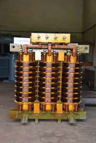 Figure 2: Custom motor starting transformer installation engineered for heavy industrial duty cycles.
 3. Global Procurement Trends in Motor Starting Systems
As global energy infrastructure transitions toward smart grids and high-efficiency electric motors, procurement teams face evolving regulatory and operational requirements. Understanding these trends ensures long-term asset value and grid compliance.
3.1 Rise of High-Efficiency IE3/IE4 Motors & Higher Inrush Ratios
Global energy regulations (such as EU Ecodesign directive and IEC 60034-30-1) mandating IE3 (Premium Efficiency) and IE4 (Super Premium Efficiency) motors have significantly impacted starting torque dynamics. IE3/IE4 motors feature reduced rotor resistance and higher magnetic flux density, resulting in locked-rotor current ratios ($I_{LRA}$) up to 8.5x to 10x rated current, compared to older IE1 motors (6x $I_{FLA}$).
Consequently, standard soft starters and undersized starters overheat rapidly when driving IE3/IE4 motors. Industrial buyers are increasingly specifying heavy-duty autotransformers with enhanced thermal time constants ($\tau$) capable of carrying 10x current for 30+ seconds without thermal degradation.
3.2 Autotransformers vs. VFDs & Soft Starters: Total Cost of Ownership (TCO)
A recurring dilemma for engineering buyers is deciding between a Motor Starting Autotransformer, a Solid-State Soft Starter, and a Variable Frequency Drive (VFD). The table below outlines the strategic decision framework:
| Evaluation Criteria | Motor Starting Autotransformer | Solid-State Soft Starter | Variable Frequency Drive (VFD) |
|---|---|---|---|
| Capital Expenditure (CAPEX) | Low to Moderate | Low | Very High (3x to 5x Autotransformer) |
| Harmonic Distortion (THD) | Zero Harmonics (Pure Sinusoidal) | High Voltage/Current Harmonics | High Harmonics (Requires Passive Filters) |
| Thermal Durability & Lifespan | 25–30+ Years (Robust Copper/Core) | 8–12 Years (Thyristor Degradation) | 7–10 Years (Capacitor/IGBT Wear) |
| Medium Voltage Application Reliability | Exceptional (High Insulation Margin) | Complex (Series Thyristor Stacks) | Requires Multi-Level Inverter Topology |
| Maintenance Complexity | Negligible Routine Inspection | Cooling Fan & PCB Repairs | Specialized Technician & Cleanroom Environment |
For fixed-speed applications (such as main water supply pumps, centrifugal compressors, mine ventilation fans, and crusher drives), autotransformers deliver the lowest TCO over a 30-year operational lifecycle by avoiding the heavy energy losses, cooling requirements, harmonic mitigation costs, and frequent component failures associated with high-power semiconductor drives.
3.3 Environmental Sustainability & Biodegradable Ester Oils
Procurement departments across Europe, North America, and Australia are prioritizing environmental ESG compliance. For oil-cooled autotransformers installed in environmentally sensitive areas (such as water treatment plants, hydro dams, and off-shore platforms), buyers are requesting natural or synthetic ester transformer fluids. Ester liquids feature high fire points ($>300^\circ\text{C}$, K-class) and complete biodegradability within 28 days, reducing environmental liability while enhancing fire safety.
4. Technological & Engineering Innovations in Modern Autotransformers
Far from being a static technology, modern motor starting autotransformers manufactured by industry leaders like Chetan Electric incorporate sophisticated mechanical, thermal, and digital design enhancements.
4.1 Finite Element Method (FEM) Thermal & Magnetic Modeling
Using advanced 3D FEM software, Chetan Electric optimizes leakage reactance, stray magnetic flux distributions, and localized hot-spot temperatures within transformer windings during short-time starting cycles. By optimizing copper conductor cross-sections and cooling duct layout, temperature rises are kept well below maximum limits, extending insulation life significantly.
4.2 Smart Condition Monitoring & IoT Integration
Modern autotransformers are equipped with digital sensor arrays that stream operational health metrics directly to plant SCADA and DCS networks:
- Fiber-Optic Winding Temperature Sensors: Provides real-time measurement of hot-spot winding temperatures during high-frequency start cycles.
- Vibration & Acoustic Signature Sensors: Detects mechanical looseness or core clamping degradation before physical damage occurs.
- Automated Tap Switch Controllers: Enables automated remote changing of starting voltage taps (e.g., switching from 65% to 80% tap under heavy start-up loads) via PLC integration.
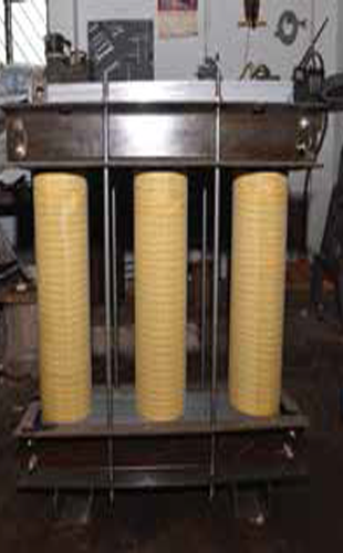 Figure 3: Rigorous factory testing and quality control on an oil-immersed industrial unit at Chetan Electric.
 5. Global Buyer FAQ: Critical Technical Answers & Intent Mining
Based on search inquiries from procurement engineers and electrical consultants worldwide, we provide authoritative answers to the top technical questions regarding motor starting autotransformers.
How do I size the KVA rating of a Motor Starting Autotransformer?
Unlike continuous-duty power transformers rated for 100% continuous load, motor starting autotransformers are short-time rated (typically rated for 10, 30, or 60 seconds). The equivalent continuous KVA rating ($KVA_{equivalent}$) is calculated based on starting current, start duration, and duty cycle frequency:
KVA_start = (sqrt(3) * V_line * I_start_motor) / 1000
KVA_continuous_equivalent = KVA_start * sqrt( t_start / t_cycle )
Where $t_{start}$ is starting duration in seconds and $t_{cycle}$ is total cycle time between starts. Chetan Electric provides custom thermal calculation sheets to ensure your autotransformer is neither undersized (leading to burnout) nor oversized (leading to unnecessary CAPEX).
Which tap setting (50%, 65%, or 80%) should be selected for my motor load?
The optimal tap depends on the load torque curve during acceleration:
- 50% Tap: Provides 25% of full starting torque and 25% line current. Ideal for unloaded starting conditions such as un-loaded centrifugal fans, air compressors with open blowdown valves, and motor-generator sets.
- 65% Tap (Most Popular Standard): Provides 42.25% starting torque and 42.25% line current. Suitable for general industrial loads including centrifugal pumps, conveyors, blowers, and HVAC compressors.
- 80% Tap: Provides 64% starting torque and 64% line current. Essential for heavy-inertia starting loads requiring high breakaway torque, such as loaded ball mills, rock crushers, positive displacement pumps, and large chillers.
Why is a Korndorfer autotransformer starter superior to a Star-Delta (Y-$\Delta$) starter?
Star-Delta starters offer a fixed voltage reduction ($57.7\%$ line voltage) yielding 33% starting torque and 33% line current. However, Star-Delta starters require a 6-lead motor, involve open-transition switching (causing massive current surges when transitioning from Star to Delta), and cannot adjust starting torque. Autotransformer starters work with standard 3-lead motors, offer adjustable starting taps (50%, 65%, 80%), and use closed-transition Korndorfer switching to eliminate current spikes entirely.
What temperature rise and insulation standards apply to autotransformers?
Under IS 2026 and IEC 60076-11, dry-type autotransformers typically utilize Class F ($155^\circ\text{C}$) or Class H ($180^\circ\text{C}$) insulation materials with a nominal design temperature rise of $90^\circ\text{C}$ to $115^\circ\text{C}$ over a $40^\circ\text{C}$ ambient. Oil-immersed units comply with Class A ($105^\circ\text{C}$) insulation with maximum oil temperature rise limited to $50^\circ\text{C}$ / $55^\circ\text{C}$. Special high-ambient designs (up to $55^\circ\text{C}$ site ambient for Middle Eastern applications) are custom-engineered by Chetan Electric.
What routine and type tests should global buyers request prior to dispatch?
Per IS 2026 / IS 1180 / IEC standards, essential routine tests include: (1) Measurement of winding resistance, (2) Voltage ratio and phase displacement verification, (3) Short-circuit impedance and load loss measurement, (4) Separate-source AC withstand voltage test, and (5) Induced overvoltage withstand test. Type tests (CPRI certified) include Short-Circuit Withstand Capability and Lightning Impulse Voltage Withstand testing.
Can motor starting autotransformers be used with continuous variable tap changers?
Standard motor starting autotransformers feature fixed off-circuit tap connections (tapped copper lugs or terminal strips). However, for applications requiring adaptive start profiles or voltage regulation during operational process changes, Chetan Electric manufactures autotransformers equipped with On-Load Tap Changers (OLTC) or motorized off-circuit tap changers controlled via Remote Tap Changer Cubicles (RTCC).
6. Company Advantages & E-E-A-T Authority: Why Choose Chetan Electric?
Selecting an experienced transformer manufacturer is critical to ensuring power system stability, motor protection, and operational safety. Chetan Electric Pvt. Ltd. brings over three decades of recognized authority, proven experience, and engineering perfection to every unit produced.
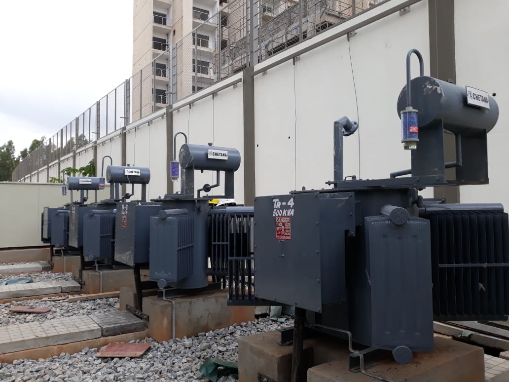 Figure 4: Heavy-duty industrial transformer completing final factory routine tests prior to global export.
 6.1 30+ Years of Engineering Mastery (Established 1994)
Founded in 1994 in Bangalore, India, Chetan Electric Pvt. Ltd. has grown from a specialized transformer workshop into a premier global exporter of power, distribution, dry-type, and motor starting autotransformers up to 5000 KVA 33kV. Our multi-decade track record ensures deep domain knowledge in handling complex industrial load dynamics.
6.2 CPRI Type-Tested Certification & ISO 9001 Compliance
Quality assurance is embedded in our engineering culture. Our transformers are independently type-tested and certified by the prestigious Central Power Research Institute (CPRI), Bangalore. Operating under an ISO 9001 certified Quality Management System, all routine, type, and special testing procedures are conducted at our state-of-the-art manufacturing plant located at Veerasandra Industrial Area, Bangalore.
6.3 Trusted by 600+ Enterprise Clients Globally
Over 600 leading public sector undertakings, multinational corporations, defense institutions, and top-tier infrastructure developers trust Chetan Electric for critical power applications. Our client roster includes:
- Government & Defense Pioneers: Indian Space Research Organisation (ISRO), Bharat Earth Movers Limited (BEML), Bharat Electronics Limited (BEL).
- Real Estate & Infrastructure Giants: Prestige Group, Sobha Developers, Puravankara Projects, Brigade Group, Raheja Group, Salarpuria Properties, Nagarjuna Construction Company (NCC).
- Public Utilities & Infrastructure: Karnataka Housing Board (KHB), KSSIDC, KIADB Projects, Panacea Hospitals.
6.4 End-to-End Customization & Comprehensive Technical Support
Unlike catalog-only suppliers, Chetan Electric specializes in 100% custom-engineered transformer solutions. Whether you require special terminal box layouts, non-standard voltage taps (e.g., 55%/70%/85%), high-altitude derating, anti-corrosive marine paint finishes, or integrated enclosure switchgear, our engineering team collaborates directly with your technical staff from initial design approval through installation and commissioning.
Summary of Quality & Compliance Standards
- ISO 9001:2015 Quality Management System Certified
- CPRI Bangalore Short-Circuit & Impulse Type-Tested
- Strict adherence to IS 2026 / IS 1180 / IS 11171 / IEC 60076 standards
- Fully equipped routine testing laboratory at Veerasandra Industrial Area, Bangalore
- Prompt international delivery with full spare parts and after-sales support