
Engineering guidelines, technical updates, and expert maintenance knowledge for industrial transformers.
In-depth analysis of oil-cooled, dry-type, and special application power distribution units.
Choosing the right High Voltage Testing Transformer is a technical decision, not a simple catalog comparison. It affects insulation verification, laboratory safety, test accuracy, and equipment service life. The IEA Electricity 2024 report expects global electricity demand to grow by about 4% annually through 2026. More substations, cables, motors, and switchgear will require dependable acceptance and maintenance testing.
A suitable transformer must match the required test voltage, frequency, power rating, waveform quality, and test-object capacitance. It should also tolerate the expected duty cycle without excessive heating. IEC 60060-1 defines key principles for high-voltage test techniques, while IEEE Std 4 provides guidance on measurement systems and test accuracy. These standards offer a strong technical foundation, but they do not replace engineering judgment. Field conditions differ.
Look beyond maximum voltage.
For example, a 100 kV unit may appear adequate for a cable test. However, the cable’s charging current can increase sharply with length and frequency. That extra burden may cause unstable voltage, overheating, or inaccurate readings. NETA ATS guidance also emphasizes controlled procedures, calibrated instruments, grounding, and documented results during acceptance testing.
Experience matters here. Operators should inspect enclosure design, interlocks, oil or resin insulation, cooling arrangements, voltage regulation, transport weight, and service support. A low purchase price can hide expensive downtime. No checklist is perfect. Reviewing real test records and consulting the manufacturer can reveal weaknesses that specifications miss. The best High Voltage Testing Transformer is therefore the one that safely matches the application, not merely the one with the highest rated voltage.
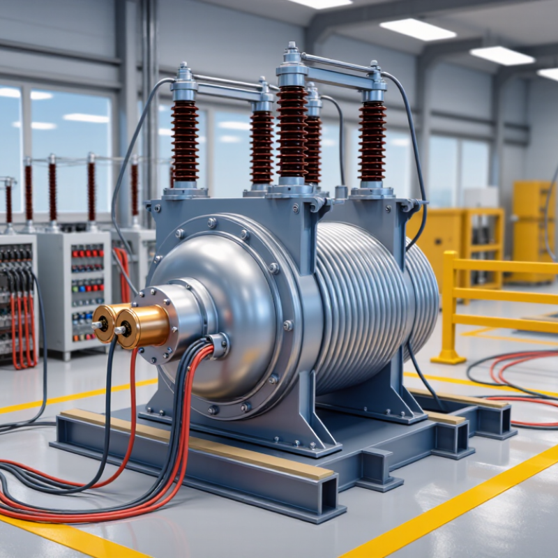
Choosing a high voltage testing transformer starts with the insulation task, not the highest available voltage. These transformers generate controlled AC voltage for checking insulation strength, leakage, and partial discharge. Oil-immersed units suit high-energy laboratory tests and repeated operation. They provide strong insulation and effective heat dissipation. However, they need careful handling, oil inspection, and a suitable enclosure.
Dry-type transformers work well in cleaner indoor environments and locations with limited fire tolerance. They are easier to maintain, but their cooling capacity may restrict long test cycles. Cascade systems connect several transformer stages when one unit cannot provide the required voltage. They are useful for testing large transformers, switchgear, and long cable sections. Resonant test systems are different. They use circuit inductance and capacitance to create high voltage with lower input power, making them practical for cable testing.
Application details should guide the final selection. A laboratory may need stable voltage control and precise measurement. A field team may value compact transport, fast setup, and rugged insulation. Check rated voltage, current, frequency, duty cycle, waveform quality, and grounding arrangements. Test equipment should match applicable IEC or IEEE requirements, with documented calibration and protective interlocks.
I have seen oversized equipment create unnecessary problems. It can increase transport risks and reduce measurement sensitivity. Small gaps, damp surfaces, or poor grounding can distort results. No selection method is perfect. Review the actual test procedure, site conditions, and failure consequences before approving the transformer.
Defining voltage, power, and insulation requirements starts with the test specimen. A catalog rating alone is not enough. IEC 60060-1 and IEEE Std 4 provide key guidance for high-voltage test methods, measurement accuracy, and atmospheric corrections. Confirm the required test voltage, waveform, duration, and frequency from the applicable equipment standard.
For a 100 kV cable test, a 120 kV transformer may appear adequate, but switching surges, measurement tolerance, and future margins can quickly reduce that reserve.
Power calculations deserve equal attention. For a capacitive load, current follows I = 2πfCV. A 200 nF specimen at 100 kV and 50 Hz draws about 6.3 A, requiring approximately 630 kVA during testing.
The transformer must tolerate this demand for the full test period, not just for a brief peak. Short-time ratings can mislead. I would calculate both steady-state and charging current, then check the control system and cooling path.
Insulation design is less visible, but often decisive. Specify clearances, creepage distances, partial-discharge limits, and the required impulse withstand level.
The U.S. Department of Energy’s recent transformer assessments place transformer losses near 2%–3% of total electricity use, showing why thermal performance matters beyond the laboratory. Still, laboratory conditions differ from field installations.
Dust, humidity, altitude, and imperfect grounding can change results. A cautious engineer should leave practical margin, while documenting every assumption for review.
How to Choose the Best High Voltage Testing Transformer
A high voltage testing transformer should protect people before it proves equipment. Look for a grounded enclosure, door interlocks, and a clearly marked emergency stop. A zero-start control prevents sudden voltage output after power returns. Discharge resistors also matter. They reduce stored energy after testing ends. In practical test rooms, visible warning lamps and physical barriers prevent careless access. Keep the testing area dry and uncluttered. Small mistakes can become serious.
Accuracy depends on more than the display. Select a system with a calibrated voltage divider and stable measuring instruments. Check its calibration records and traceability to recognized measurement standards. The meter should remain readable during gradual voltage increases. Ripple, temperature rise, and load changes can affect results. A transformer that looks precise may still produce misleading readings. That is easy to miss.
The control system should provide smooth ramping, current limits, and automatic shutdown. Remote operation keeps personnel away from energized equipment. Data logging helps compare test results and identify gradual insulation changes. However, software controls are not enough. Operators still need clear procedures, training, and independent safety checks. Test the emergency stop regularly, not only during annual maintenance. I would also inspect cables, grounding points, and connectors before every session. No design removes human error completely. That uncomfortable fact deserves attention.
| Evaluation Dimension | Recommended Specification or Benchmark | Why It Matters | How to Verify | Selection Priority |
|---|---|---|---|---|
| Rated Test Voltage | Select a transformer with a rated output at least 10–20% above the required test voltage, subject to the applicable test standard. | Provides operating margin and reduces stress caused by continuous operation near the maximum rating. | Compare the nameplate rating, voltage waveform requirements, duty cycle, and the actual test voltage specified by the test procedure. | Critical |
| Rated Output Capacity | Choose sufficient kVA for the test object, including capacitive charging current and any required test duration. A practical design margin is commonly 20–30%. | Insufficient capacity can cause voltage sag, overheating, nuisance trips, or unstable test results. | Calculate approximate charging current using I = 2πfCV for an AC capacitive load, then compare it with the transformer and control-system ratings. | Critical |
| Insulation and Enclosure | Use insulation and clearances suitable for the maximum operating voltage, environment, altitude, and pollution level. An earthed enclosure or guarded test area is strongly recommended. | Reduces the risk of flashover, accidental contact, and insulation failure during high-voltage operation. | Review insulation coordination, creepage and clearance documentation, enclosure design, and environmental ratings. | Critical |
| Grounding and Discharge Circuit | Provide a dedicated protective earth, visible grounding connections, and a rated discharge path for stored energy. Automatic discharge should be supported by a verified manual grounding procedure. | Test objects and cables can retain dangerous charge after the high-voltage output is switched off. | Check grounding conductor size, discharge resistor ratings, discharge time, grounding-stick provisions, and interlock operation. | Critical |
| Door, Gate, and Area Interlocks | The high-voltage circuit should be prevented from energizing when an access door or test-area gate is open. Interlocks should be fail-safe and monitored. | Prevents personnel access to energized equipment and detects unsafe access conditions. | Open each access point during setup and operation simulations; confirm that high voltage cannot start or is immediately removed. | Critical |
| Emergency Stop Function | Use a clearly visible, manually reset emergency-stop device that removes high-voltage excitation and prevents automatic restart. | Allows rapid shutdown during insulation breakdown, unexpected arcing, or personnel emergencies. | Activate the emergency stop under controlled conditions and confirm power removal, alarm indication, and manual-reset behavior. | Critical |
| Voltage Measurement Accuracy | For routine withstand testing, a calibrated high-voltage divider and measuring system with an overall uncertainty appropriate to the test standard; Class 0.5 or 1.0 performance is commonly used for general laboratory applications. | Accurate voltage measurement is essential for valid pass/fail decisions and repeatable test records. | Request calibration certificates, uncertainty budgets, divider ratios, frequency range, and traceability to national or international standards. | High |
| Current Measurement and Trip Threshold | Use a measurement range suitable for normal leakage current and fault current, with adjustable overcurrent protection and a clearly defined trip response. | Detects breakdowns and abnormal loading while avoiding unnecessary trips caused by normal capacitive current. | Verify sensor range, accuracy, response time, trip threshold, and behavior under simulated leakage and short-circuit conditions. | Critical |
| Voltage Ramp and Regulation | Provide adjustable ramp-up and ramp-down control, preferably with programmable dwell time and voltage regulation suitable for the test load. | Controlled ramping limits transient stress and improves repeatability between operators and test cycles. | Test multiple ramp rates and load conditions; record voltage stability, overshoot, and repeatability. | High |
| Zero-Start and No-Automatic-Restart | The controller should require the output control to return to zero before energizing and should block automatic restart after a trip, power interruption, or interlock opening. | Prevents unexpected application of high voltage when the system is restarted or a fault is cleared. | Interrupt the supply and open an interlock during testing; confirm that restart requires deliberate operator action at zero output. | Critical |
| Test Timer and Dwell Control | Use a timer with adjustable test duration and an automatic controlled return to zero at the end of the dwell period. | Improves consistency and reduces the chance of applying test voltage longer than required. | Compare timer settings with the test procedure and verify end-of-test shutdown, alarm, and discharge sequence. | High |
| Waveform and Frequency | For power-frequency AC tests, select a 50 or 60 Hz system as required. The output should have a stable waveform with distortion appropriate to the applicable test method. | Frequency and waveform affect dielectric stress, charging current, measurement accuracy, and test comparability. | Measure frequency and waveform using calibrated instruments under no-load and representative-load conditions. | High |
| Control Interface and Data Logging | Choose a controller with clear status indication, password-protected settings where needed, event logging, and exportable voltage, current, time, and trip data. | Creates an auditable test record and helps identify intermittent faults or operator errors. | Review sample reports, timestamp accuracy, data resolution, storage capacity, user permissions, and communication-interface security. | High |
| Thermal Protection and Duty Cycle | Include temperature monitoring, overload protection, cooling appropriate to the kVA rating, and a clearly stated intermittent or continuous duty cycle. | Prevents insulation aging and premature failure during repeated or extended testing. | Review temperature-rise data, cooling requirements, overload settings, duty-cycle limits, and alarm history. | High |
| Calibration and Verification | Plan periodic calibration of voltage and current measurement channels. The interval should be risk-based, with annual verification commonly used in controlled laboratory environments. | Maintains measurement confidence and supports traceable quality records. | Check calibration scope, uncertainty, adjustment limits, reference standards, certificates, and recommended maintenance interval. | High |
| Applicable Standards and Documentation | The design and test procedure should be assessed against relevant requirements such as IEC 60060-1 for high-voltage test techniques and applicable electrical-equipment safety requirements. | Standards provide a consistent basis for safety, measurement methods, test levels, and acceptance criteria. | Request the user manual, wiring diagrams, risk assessment, conformity documentation, factory-test records, and calibration reports. | Critical |
| Operator Usability and Training | Select a system with unambiguous controls, visible high-voltage indicators, documented operating steps, and training for setup, discharge, grounding, and emergency response. | Human-factor controls reduce setup errors and help ensure that safety functions are used correctly. | Conduct a supervised operating demonstration and verify that two-person checks, warning labels, procedures, and training records are available. | Critical |
Transformer construction directly affects testing stability, safety, and maintenance effort. Oil-insulated transformers often handle demanding voltage levels and continuous operation effectively. However, they need leak checks, oil-quality testing, and careful storage. Dry-type transformers reduce fluid-related maintenance and suit cleaner indoor environments. They may require stronger ventilation and closer temperature monitoring.
Construction is only one part of the decision. Mobility matters.
A compact transformer with locking wheels can simplify movement between test areas. Check its lifting points, cable storage, and overall balance before purchase. A lightweight design may improve transport but could reduce mechanical stability. Estimate doorway widths, floor strength, and available power connections. These details are easy to overlook.
Maintenance planning should include insulation inspections, terminal cleaning, grounding checks, and calibration records. Use procedures based on applicable electrical safety standards and the manufacturer’s technical documentation. Field teams sometimes focus on maximum voltage and ignore service access. That is an expensive mistake.
Tips: Ask for a maintenance schedule before buying. Inspect hinges, wheels, meters, and protective enclosures. Confirm replacement parts are available locally. Keep clear test records. If the unit feels difficult to move during a trial, it will probably become harder after installation. A stronger inspection routine is usually better than a perfect specification sheet.
How to Choose the Best High Voltage Testing Transformer
Selecting a reliable supplier requires more than comparing purchase prices. Look beyond the quote. Request routine-test records, calibration traceability, insulation data, thermal-rise results, and compliance with IEC 60060-1 or relevant IEEE practices. A supplier should explain the transformer’s duty cycle, cooling method, voltage stability, and protection response in practical terms. Ask for service-response times, spare-part availability, operator training, and documented factory acceptance procedures. These details reveal whether the equipment is designed for daily testing or occasional demonstration use.
Total operating cost deserves equal attention. Include electricity consumption, oil inspection, preventive maintenance, calibration, installation, transport, insurance, and planned downtime. The International Energy Agency’s Electricity Grids and Secure Energy Transitions report estimates that annual grid investment must exceed 600 billion dollars by 2030. Testing capacity will face similar pressure. Efficient equipment can therefore reduce repeated test delays and energy waste. The U.S. Department of Energy’s 2024 distribution-transformer rule projects about 3.6 quadrillion British thermal units in energy savings over 30 years. That figure concerns distribution transformers, not testing units, but it provides a useful efficiency benchmark. One uncomfortable lesson remains: a cheaper transformer may create higher costs through unstable output, frequent calibration, or long service delays. Build a five-year cost model, then challenge every assumption. Estimates are often too optimistic.
Start with the insulation task, not the highest available voltage. Confirm test voltage, waveform, frequency, duration, and specimen type. Leave practical margin for switching surges and measurement tolerance. More voltage is not always better.
Oil-immersed units suit repeated, high-energy laboratory tests. The oil provides strong insulation and helps remove heat. They require oil inspections, careful handling, and a suitable enclosure. Maintenance cannot be ignored.
Dry-type units fit clean indoor rooms and sites with limited fire tolerance. They are easier to maintain and avoid insulating oil. Their cooling capacity may limit long testing cycles. Check temperature rise carefully.
Cascade systems connect several transformer stages to produce higher voltage. They suit large transformers, switchgear, and long cable sections. The arrangement needs careful insulation coordination and grounding. Setup can become bulky.
Resonant systems use inductance and capacitance to create high voltage. They usually require less input power than conventional arrangements. This makes them practical for testing capacitive cable sections. The circuit still needs accurate tuning.
Use the relationship I = 2πfCV for capacitive current. For example, a 200 nF specimen at 100 kV and 50 Hz draws about 6.3 A. That equals roughly 630 kVA during testing. Check steady-state and charging current.
Look for a grounded enclosure, door interlocks, warning lamps, and an emergency stop. A zero-start control prevents sudden output after power returns. Discharge resistors reduce stored energy after testing ends. Keep the area dry and uncluttered.
Use a calibrated voltage divider and traceable measuring instruments. Review calibration records before approving the equipment. Check ripple, temperature rise, grounding, and load changes. A precise display can still mislead.
Inspect cables, connectors, grounding points, barriers, and interlocks. Confirm smooth voltage ramping, current limits, and automatic shutdown. Remote operation keeps personnel farther from energized equipment. Test the emergency stop regularly.
No. Oversized equipment may increase transport risks and reduce measurement sensitivity. Small gaps, damp surfaces, and poor grounding can distort results. Review site conditions, failure consequences, and the actual procedure. No selection method is perfect.
Choosing the right High Voltage Testing Transformer requires a clear understanding of the equipment’s intended applications and testing environment. Start by comparing suitable transformer types, such as oil-insulated, dry-type, or portable designs, according to the voltage levels, power capacity, insulation requirements, and frequency range needed. The transformer should provide stable output and sufficient margins for reliable testing without unnecessary energy consumption.
Safety, accuracy, and control are equally important. Look for effective protection against overloads, short circuits, excessive temperature, and unexpected voltage changes, along with precise measurement and user-friendly control systems. Construction quality, mobility, cooling, maintenance access, and replacement-part availability can strongly influence long-term usability. Finally, evaluate suppliers based on technical support, documentation, warranty coverage, delivery capability, and compliance with applicable testing standards. Comparing purchase price with installation, operation, maintenance, and downtime costs will help identify the most dependable and economical solution for your testing requirements.