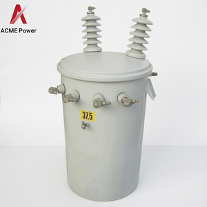

Explore our specialized lineup of high-precision oil-immersed, pole-mounted, pad-mounted, and dry-type power transformers engineered to stringent IEC 61869-3 and IEEE C57 standards for global utility and industrial buyers.
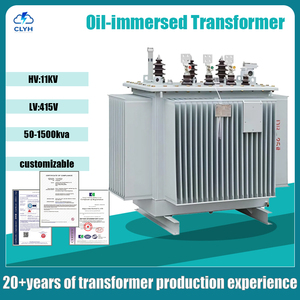
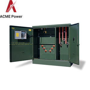
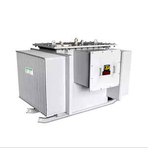
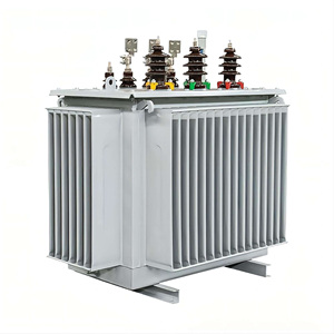
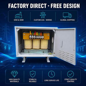
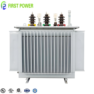
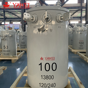
In modern electrical grid architectures, high-voltage transmission networks, and heavy industrial distribution substations, the Potential Transformer (PT)—interchangeably designated as a Voltage Transformer (VT)—serves as an indispensable instrument of grid safety, metrological precision, and protective relaying. Operating at the intersection of electromagnetic conversion and digital signal processing, potential transformers step down lethal medium-voltage (MV) and high-voltage (HV) system levels to standardized, manageable secondary values (such as 110V, 100V, or 110/√3V). This precise scaling allows protective relays, revenue metering equipment, and digital fault recorders to evaluate line parameters safely and continuously.
As global energy grids undergo rapid decarbonization, digitize via IEC 61869/61850 protocols, and integrate variable renewable energy (VRE) assets like offshore wind and utility-scale solar PV, the performance benchmarks for Potential Transformers have shifted dramatically. Procurement directors, electrical EPC engineers, and substation asset managers no longer evaluate PT suppliers solely on upfront cost. Instead, modern intent-driven technical audits demand robust verification of CE Marking compliance (Low Voltage Directive 2014/35/EU and EMC Directive 2014/30/EU), extended thermal stability classes, strict ferroresonance suppression capabilities, and low-partial-discharge dielectric insulation profiles.
Selecting a CE-certified potential transformer factory requires verifying more than basic ratio accuracy. Advanced engineering procurement must evaluate the knee-point voltage of the magnetic core, insulation loss factor (tan δ), thermal withstand capability during system earth faults, and compliance with severe atmospheric pollution standards (IEC 60815 creepage ratios ≥ 31 mm/kV).
With an established footprint originating from specialized transformer manufacturing hubs and serving over 600 global enterprises, our production ecosystem represents thirty years of continuous metallurgical, thermal, and dielectric innovation.
Every custom transformer topology undergoes comprehensive routine, type, and special testing. Certified by the Central Power Research Institute (CPRI) and aligned with IS 2026 / IS 1180 / IS 11171 / IEC 61869 standards, our products guarantee zero latent dielectric defects before overseas dispatch.
Utilizing ultra-low loss, high-permeability Cold-Rolled Grain-Oriented (CRGO) silicon steel laminations with step-lap mitered joints, our potential transformers achieve minimal magnetizing currents, ultra-low core losses, and immunity to harmonic saturation.
Our manufacturing protocols strictly implement European CE Directives. Featuring reinforced insulation system designs, robust electromagnetic compatibility (EMC) shielding, and pressure-relief mechanisms, our units seamlessly clear European port inspections and site commissioning audits.
Inductive potential transformers connected to ungrounded or insulated neutral networks face inherent ferroresonance risks triggered by switching transients. We integrate optimized damping circuits and anti-ferroresonance secondary windings to prevent thermal runaway and dielectric breakdown.
Engineering custom step-down ratios ranging from 33kV/110V down to single-phase pole-mounted 6.3kV/110V configurations. We manufacture dual-purpose units equipped with dedicated cores for Class 0.2S revenue metering alongside Class 3P/6P protective relaying cores.
Trusted by industry giants such as Prestige Group, Sobha Developers, ISRO, BEML, and BEL. Our robust transformer fleet operates under demanding environmental conditions across real estate developments, defense facilities, heavy furnace plants, and mining complexes.
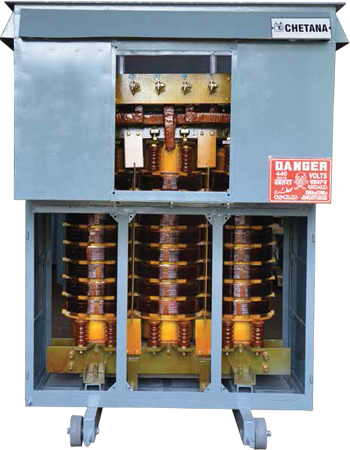
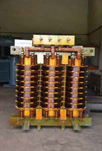
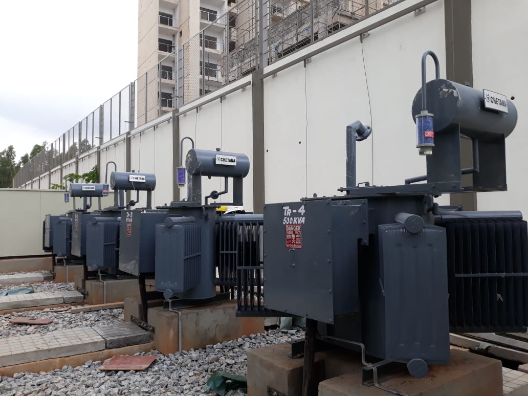
To assist utility procurement specialists and electrical consultants in technical selection, the table below contrasts Electromagnetic Potential Transformers against alternative voltage measurement topologies.
| Performance Parameter | Inductive Potential Transformer (PT) | Capacitive Voltage Transformer (CVT) | Optical / Electronic Voltage Sensor |
|---|---|---|---|
| Primary Voltage Range | Up to 72.5 kV (Ideal for MV & Sub-T) | 110 kV to 765 kV (EHV / UHV) | 10 kV to 400 kV (Digital Substation) |
| Accuracy Class Range | 0.1, 0.2S, 0.5 (Ultra-High Stability) | 0.2, 0.5 (Frequency Sensitive) | 0.2, 0.5S (Wide dynamic range) |
| Frequency Response | DC to High Harmonics (Flat Curve) | Resonant near 50/60Hz (Band-limited) | Wideband (KHz range) |
| Transient Phase Shift | Negligible (< 5 minutes of arc) | Moderate during line switching | Zero (Digital processing) |
| Ferroresonance Vulnerability | Mitigated via Dampening Cores | High (Requires specialized dampening) | Immune (Non-magnetic) |
| Primary Application | Industrial Metering, Breaker Control, MV Grid | EHV Transmission Line Protection | IEC 61869-9 Smart Grid Merging Units |
| CE Certification Standard | IEC 61869-3 / EN 61869-3 / LVD Compliant | IEC 61869-5 / EN 61869-5 | IEC 61869-11 / EN 61869-11 |
Traditional oil-immersed distribution and potential transformers relied heavily on conventional mineral oils. However, global ESG mandates and municipal fire safety regulations (especially in high-density urban substations and indoor commercial complexes) are driving rapid adoption of Synthetic and Natural Ester Liquids (IEC 61099 compliant). Ester fluids offer flashpoints exceeding 300°C (Class K insulation), self-extinguishing flame properties, and 100% biodegradability. Exporters capable of supplying ester-filled or high-grade Vacuum Pressure Impregnated (VPI) dry-type potential transformers hold a decisive competitive advantage in European and North American markets.
The global shift toward IEC 61869-9/13 process-bus architectures is transforming how voltage signals are transmitted across substations. Modern potential transformers are increasingly paired with field-mounted Merging Units (MUs) that convert analog 110V secondary outputs into sampled values (SV) sent via fiber-optic Ethernet cables. Factory integration testing must ensure that PT secondary phase offsets and ratio errors remain non-existent across operating temperature envelopes (-40°C to +65°C), preventing false trips in differential protection schemes.
With the proliferation of Gas-Insulated Switchgear (GIS) and rapid vacuum circuit breaker switching, potential transformers are frequently subjected to Very Fast Transient Overvoltages (VFTO). These high-frequency oscillations (up to tens of MHz) generate severe inter-turn voltage stress on primary windings. Leading export manufacturers employ advanced finite element electro-magnetic modeling (FEM) to optimize layer insulation distribution, applying electrostatic shielding screens between primary and secondary turns to bypass high-frequency surge spikes harmlessly to ground.
Modern B2B procurement evaluations prioritize Total Cost of Ownership (TCO) calculated over a 30-year operational lifecycle over nominal initial purchase price. The TCO equation incorporates core continuous no-load losses, copper winding load losses, routine oil testing costs, and transformer recycling footprint. By specifying high-grade amorphous alloys or ultra-thin CRGO steel, potential transformer factories can reduce lifetime no-load losses by up to 60%, yielding massive energy savings for power utilities.
Direct answers to critical technical and commercial questions encountered during potential transformer selection, factory auditing, and international importation.
CE Certification confirms that a potential transformer complies with European Union health, safety, and environmental protection standards. Specifically, it requires adherence to the Low Voltage Directive (LVD 2014/35/EU) and Electromagnetic Compatibility Directive (EMC 2014/30/EU), validated via harmonized standards like EN 61869-1 and EN 61869-3. Certification involves third-party factory audits, comprehensive insulation dielectric breakdown tests, and temperature rise verification.
The selection depends entirely on the secondary device connected:
• Class 0.1 / 0.2 / 0.2S: Specified for high-precision revenue metering, tariff billing, and laboratory calibration standards.
• Class 0.5: Used for commercial energy metering, panel instruments, and general monitoring.
• Class 3P / 6P: Engineered for protective relaying (e.g., overvoltage, distance, or earth-fault relays), ensuring accurate ratio performance up to the voltage factor limit during system faults.
Rated Burden (expressed in Volt-Amperes, VA) represents the maximum load connected to the secondary winding (including relays, meters, and connecting cable impedance) that the PT can drive while maintaining its guaranteed accuracy class. Specifying an oversized burden (e.g., 100VA when load is only 5VA) can cause the transformer to operate outside its calibrated accuracy envelope. Modern digital relays consume minimal power (<1VA), making 5VA to 15VA burdens optimal for accuracy matching.
We employ a multi-layered anti-ferroresonance design strategy. First, primary flux density is capped well below core saturation levels during overvoltage conditions (typically <1.5 Tesla at 1.9x rated voltage). Second, we offer tertiary open-delta windings connected to a non-linear dampening resistor (damping burden) that absorbs resonant oscillation energy without causing excessive thermal dissipation during normal operations.
In accordance with IEC 61869-3 and IS 2026/1180, 100% of manufactured units undergo strict routine testing:
1. Verification of terminal markings and polarity.
2. Power-frequency voltage withstand test on primary and secondary windings.
3. Induced overvoltage withstand test.
4. Partial discharge measurement (ensuring <10 pC at rated voltage).
5. Determination of ratio error and phase displacement across 80% to 120% of rated voltage.
Yes. As a custom transformer engineering factory, we specialize in drop-in replacement units for obsolete legacy substations. We can match historical footprint dimensions, primary terminal arrangement height, secondary terminal box IP protection ratings (IP55/IP66), and multi-tap secondary ratio configurations (e.g., 11kV:110V/63.5V dual-tap) without altering existing civil foundations.
Whether you require standard 11kV distribution transformers, 33kV outdoor oil-immersed voltage transformers, or specialized pole-mounted units for regional grid expansions—our engineering team delivers type-tested reliability, competitive direct-from-factory pricing, and complete technical documentation.
Inquire Now