
Explore our precision-engineered distribution and high-frequency power transformers manufactured to rigorous international standards with CPRI verification.
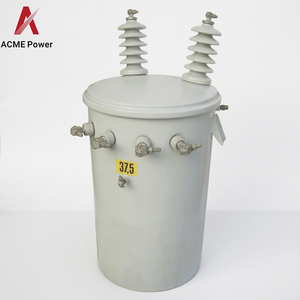
Rugged overhead distribution transformer designed for Latin American power networks, featuring high dielectric oil insulation and reduced core losses.
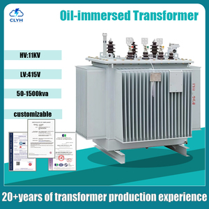
Heavy-duty industrial step-down series built with step-lapped grain-oriented silicon steel cores for max electrical efficiency and heat dissipation.
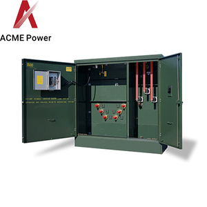
Fully enclosed pad-mounted transformer featuring ONAN/ONAF dual-cooling capabilities and Dyn11 vector configuration for commercial utility grids.
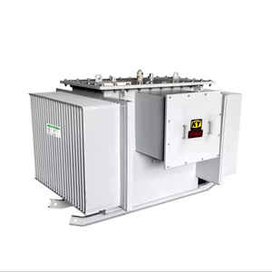
Hermetically sealed energy-efficient transformer delivering low no-load noise, zero-maintenance tank architecture, and low short-circuit stress.
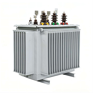
Multi-rating primary grid distribution transformers engineered for high-voltage substations, mining facilities, and heavy industrial plants.
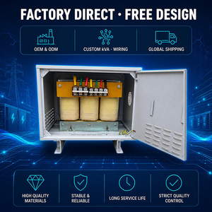
High-voltage test transformer unit configured for specialized power frequency testing, rectifier equipment, and custom motor starting duty.
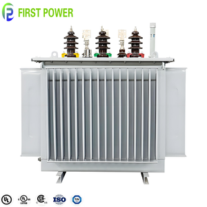
20kV medium-voltage oil-immersed distribution series optimized for tight thermal control, minimized stray flux losses, and enhanced insulation endurance.
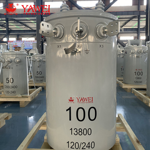
Precision 13.8kV single-phase pole mounted unit featuring dual secondary voltage taps, corrosion-resistant tanks, and long-term grid stability.
Blending 30+ years of transformer engineering excellence with ISO 9001 certified manufacturing facilities, modern testing laboratories, and tailored global export logistics.
All transformer design configurations are type-tested at the Central Power Research Institute (CPRI), ensuring short-circuit resistance, impulse withstand voltage, and maximum dielectric integrity.
Fully compliant with international standards including IS 2026, IS 1180, IS 11171, and IEC 60076. Routine tests are executed in-house using automated precision testing benches.
From SMPS high-frequency ferrite core transformers and planar PCB transformers to 5000 KVA 33kV distribution units, furnace transformers, and rectifier equipment.
Trusted by over 600 global enterprises across infrastructure, real estate (Prestige Group, Sobha, Brigade), defense organizations (ISRO, BEL, BEML), and heavy industrial complexes.
Engineered high-frequency testing transformers up to 150kV for power frequency tests, constant voltage transformers (CVT), and automatic voltage relay (AVR) integrated systems.
Complete control over raw material procurement—utilizing high-permeability MnZn ferrites, electrolytic copper, triple-insulated wires, and high-vacuum oil filling process.
In contemporary power electronics, the demand for compact, high-efficiency energy conversion has driven a structural transition from conventional line-frequency (50/60Hz) transformers toward high-frequency (HF) switching magnetics operating between 20 kHz and beyond 3 MHz. Selecting the best high-frequency factory and suppliers in China requires a comprehensive understanding of the magnetic core dynamics, switching losses, and thermal topologies that govern high-density power supplies (SMPS), electric vehicle (EV) charging stations, solar microinverters, and industrial induction heating systems.
High-frequency operation fundamentally alters transformer design physics. While classical transformers are limited by magnetic flux saturation limits ($B_{max}$) of silicon steel sheets, high-frequency transformers operate under magnetic material loss limitations characterized by the Steinmetz Equation:
To minimize core loss at elevated frequencies, premier Chinese manufacturers utilize advanced Soft Magnetic Materials (SMM), primarily Manganese-Zinc (MnZn) Ferrites, Nickel-Zinc (NiZn) Ferrites, and Nanocrystalline Ribbon Cores. Below is an engineering overview of magnetic material behavior across spectrums:
MnZn Ferrite (PC47 / N97) Nanocrystalline (100kHz High Permeability) Amorphous Metal Cores Planar Matrix Core StructuresAt frequencies above 50 kHz, copper conductors undergo severe AC resistance increases due to electromagnetic field interactions. Leading high-frequency transformer suppliers employ specialized winding geometries and wire technologies to counteract two primary phenomena:
The skin effect restricts alternating current flow to the outer skin of a conductor. The skin depth ($\delta$) decreases inversely with the square root of frequency:
To maintain an $R_{ac} / R_{dc}$ ratio close to 1.0, high-frequency factories employ Litz wire—consisting of individually insulated strands twisted in precise woven patterns—or copper foil windings with thickness tuned to $\le 2\delta$.
Proximity effect occurs when magnetic fields generated by adjacent conductor turns induce eddy currents within neighboring wires, leading to exponential copper loss escalation. Advanced Chinese OEM factories utilize Interleaved Winding Configurations (such as Primary-Secondary-Primary / P-S-P sandwich structures or matrix planar windings). Interleaving reduces the magnetomotive force (MMF) spatial buildup within transformer window areas, suppressing proximity loss by up to 70% and minimizing leakage inductance ($L_{lk}$).
The commercialization of Wide Bandgap (WBG) power devices—specifically Gallium Nitride (GaN) HEMTs and Silicon Carbide (SiC) MOSFETs—has pushed power supply switching frequencies into the megahertz range. Traditional wire-wound transformers often fail at these frequencies due to excessive parasitic capacitance and thermal bottlenecks.
To leverage WBG speeds, premier China suppliers manufacture Planar Transformers. Planar designs replace discrete wire coils with multi-layer printed circuit board (PCB) traces embedded inside flat ferrite cores (E-PL, PQ-PL geometries).
| Transformer Architecture | Operational Frequency Range | Power Density ($W/cm^3$) | Typical Efficiency | Primary Technical Advantages |
|---|---|---|---|---|
| High Frequency Ferrite (Wire-Wound) | 20 kHz – 300 kHz | 5 – 15 W/cm³ | 94.5% – 97.5% | Cost-effective, highly customizable turn ratios, ideal for standard industrial SMPS. |
| Planar PCB Transformer | 100 kHz – 3.0 MHz | 25 – 50+ W/cm³ | 98.5% – 99.4% | Ultra-low profile, perfect parasitic repeatability, excellent heat dissipation via cold plates. |
| Nanocrystalline Power Transformer | 10 kHz – 100 kHz | 15 – 30 W/cm³ | 98.0% – 99.1% | High saturation flux density ($B_s = 1.25T$), wide thermal stability (-40°C to +130°C). |
| Conventional Oil-Immersed Distribution | 50 Hz / 60 Hz | 0.1 – 0.5 W/cm³ | 98.0% – 99.5% | High dielectric strength, continuous heavy power grid stepping (Up to 5000kVA, 33kV). |
When evaluating high-frequency transformer suppliers and power manufacturing partners in China, procurement teams must look beyond basic unit pricing. Achieving long-term supply chain reliability and zero defect rates (PPM < 10) requires rigorous vendor audit protocols:
As global power grids digitize and industrial automation accelerates, the procurement landscape for transformers is undergoing three major shifts:
1. Microgrid & Solar Integration: Sourcing high-frequency isolation transformers tailored for Phase-Shifted Full-Bridge (PSFB) and LLC resonant converters in battery energy storage systems (BESS).
2. Total Cost of Ownership (TCO) Prioritization: Industrial buyers are prioritizing transformers engineered with ultra-low no-load ($P_0$) losses. Over a 20-year operational lifecycle, energy loss reduction yields savings that far exceed initial equipment capital expenditure (CAPEX).
3. Modular & Solid-State Transformers (SST): Hybrid topologies combining high-frequency ferrite magnetic links with medium-voltage power electronics are replacing bulky traditional distribution transformers in space-constrained urban substations.
Expert technical answers to common B2B procurement, design specification, and factory qualification inquiries.
For frequencies between 100 kHz and 1 MHz, Manganese-Zinc (MnZn) power ferrites (such as PC47, PC95, or equivalent grades) offer the optimal balance of high saturation flux density ($B_s \approx 410-510 mT$) and low volumetric loss density ($P_v$). Above 1 MHz, Nickel-Zinc (NiZn) ferrites or planar PCB copper trace topologies are recommended.
Central Power Research Institute (CPRI) type tests subject transformers to extreme short-circuit stress, lightning impulse voltages (BIL testing), and thermal rise limits. CPRI verification certifies that a transformer design can withstand severe grid transients without mechanical winding deformation or dielectric insulation breakdown.
Litz wire consists of multiple individually insulated copper strands twisted together. Because high-frequency AC current tends to flow only on the outer conductor surface (skin effect), bundling smaller strand diameters below the skin depth ($\le \delta$) ensures uniform current distribution, lowering AC resistance ($R_{ac}$) and reducing operating temperature.
An actionable RFQ should specify: Primary/Secondary Voltages, Power Rating (kVA or Watts), Operational Frequency Range, Vector Group (for 3-phase units like Dyn11), Cooling Method (ONAN/ONAF/VPI/Dry), Maximum Permissible Dimensions, Temperature Rise Limits, and Required International Standards (IS 2026, IEC 60076, UL).
Planar transformers feature extremely low profile heights (down to 10mm), superior thermal power density (up to 50W/cm³), exceptional parasitic parameter consistency due to automated PCB manufacturing, and minimal leakage inductance, making them ideal for high-density GaN and SiC power supplies.
Standard prototype sample manufacturing typically requires 7 to 14 days. Volume production orders for custom high-frequency ferrite transformers or oil-immersed distribution transformers up to 5000 kVA generally range from 3 to 6 weeks, inclusive of full factory routine testing and export packaging.